Spdt Relay Wiring Diagram Datsun

Bosch 5 Pin Relay Wiring Diagram To Driving Light And Wiring

Kg 7910 Rib 2401d Dpdt Relay Wiring Diagram Schematic Wiring

Online Led Store 10 Pack 12v 30 40 Amp 5 Pin Spdt Bosch Style

12v 30 40 Amp 5 Pin Spdt Automotive Relay With Wires Harness

Best Relay Wiring Diagram 5 Pin Wiring Diagram Bosch 5 Pin Relay

Pin On Wiring Chart Picture

When there is.
Spdt relay wiring diagram datsun. This video will explain how a relay works. The single pole double throw spdt relay is quite useful in certain applications because of its internal configuration. The red led now shuts off and the green led turns on. One can be normally closed and the other one is opened or it can be normally open and the other one closed.
Typical relay typical relay contains electromagnetic coil n o contact n c contact and. How does a relay work spdt dpdt spst automotive relay dial2fast. This page demonstrates several simple ways to wire a relay for various applications. When the coil of the relay is at rest not energized the common terminal and the normally closed terminal have continuity.
This is the diagram below to learn all the pin terminals of a single pole double throw spdt relay. Diagrams will show how multiple relays one relay or another or just one relay can control your device. So basically you can see the spdt relay as a way of switching between 2 circuits. Relay wiring mekaniko duration.
The next diagram figure 3 shows the relay with the coil energized. Relay terminals relay wiring diagrams spdt relay wiring diagram. The 2 coil terminals is where the voltage is placed in order to energize the coil. That s what the curly looking symbol means.
All examples shown are for spdt single pole double throw relays which includes any of the 5 10 or 20 amp relays on this site. I recently ran into a wiring problem and made an illustrated post on how i figured out the solution and some guesses as to why i came to the solution i did. It has one common terminal and 2 contacts in 2 different configurations. One of the most common pieces of circuit bending hardware is the single position dual throw spdt switch.
When the 5 v is disconnected from the coil a spring in the relay causes it to switch back to the other state. The spdt relay 30a is a high quality single pole double throw relay spdt the relay consists of a coil 1 common terminal 1 normally closed terminal and one normally open terminal. The no terminal of the relay gets power only when the relay is powered. Share on tumblr relay is a electro mechanical switch used to control high power application through low power signal electronic circuits for an example a simple timer circuit working under 5v dc bias can not control high voltage light bulb by introducing relay component we can easily control light bulb.
The two pins in the bottom left of the pin diagram are the coil. Place the relay s rated coil voltage on these terminals. The diagram below figure 2 shows an spdt relay at rest with the coil not energized. When the relay receives 12 volts of power the relay s snaps from the nc position to the no position.

How To Wire A Relay For Off Road Led Lights Off Road Led Lights
Electric Fans With Relay Wiring Automotive Mechanic Electric

Electrical Repair Services With Images Automotive Electrical
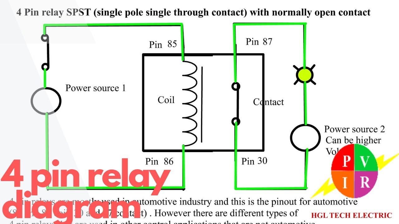
4 Pin Relay Diagram 4 Pin Relay Wiring 4 Pin Relay Animation 4

12v 30 Amp Relay Wiring Diagram Electrical Circuit Diagram

4 Pin Relay Wiring Diagram Autok

12v 5 Pin Relay Wiring Diagram Fitfathers Me Also Blurts Me

Images Of Wiring Diagram For Horn Relay Harley Davidson A New
